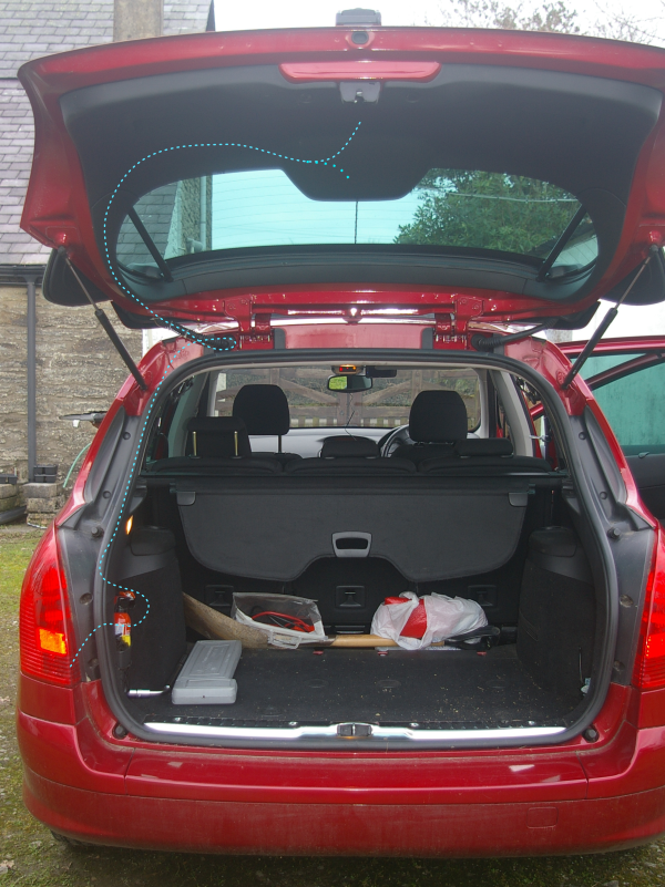
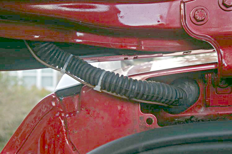
Overview of wiring route.
with the camera fitted above or below the number plate.
Stage C - Removing the panels from inside the rear door.
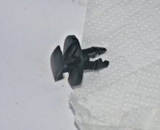
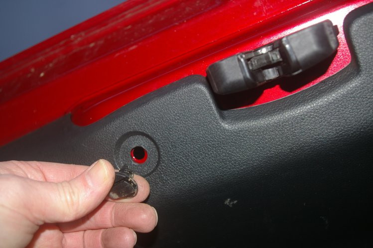
This is one of the fiddly little clips which you will find holding some of the panel.
You will need to remove them by levering up the centre section and then pulling out the whole clip.
This is the wiper cover which is first to be removed.
It just pulls up.
This is an inside view of the wiper cover.
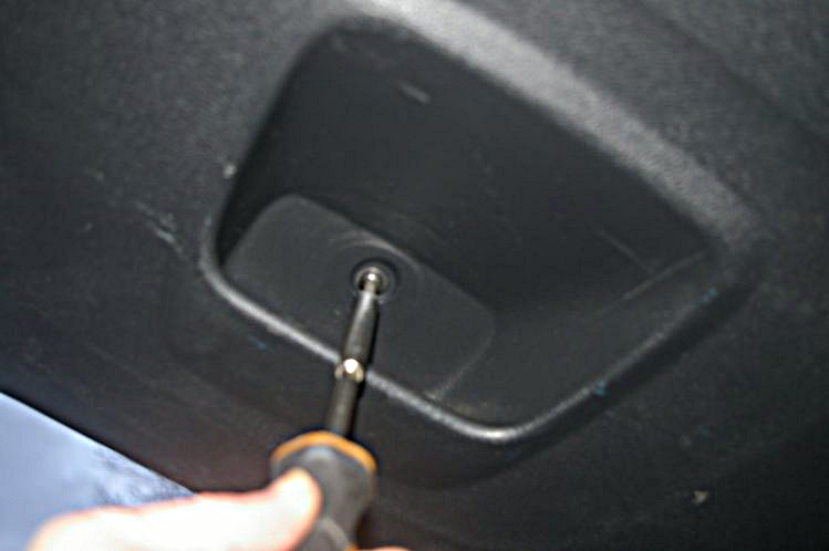
Once the wiper mechanism cover is off you can get at the first bolt holding the main panel in place.
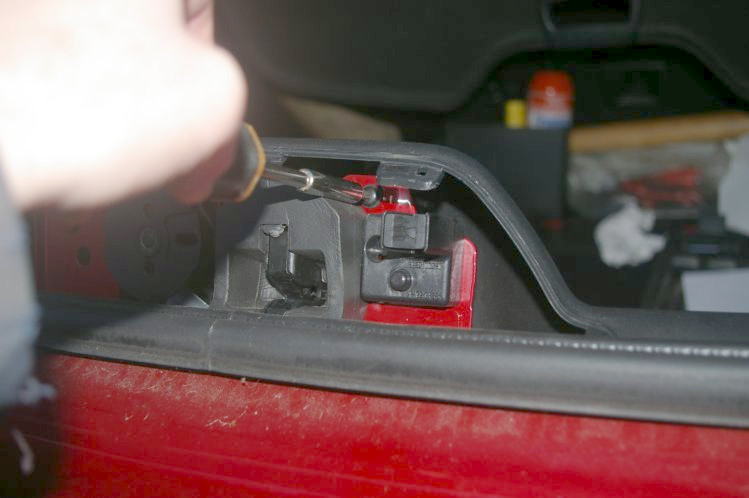
Now for the top panel which should just unclip, giving you access to the bolts holding the side panels - as shown.
You will need to remove both side panels.
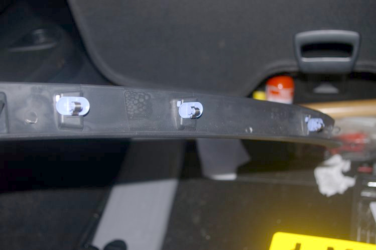
Here is an inside view of one of the side panels.
With the side panels off you can get at the first two of the bolts holding the main panel.
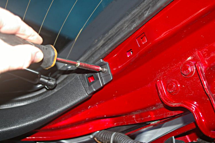
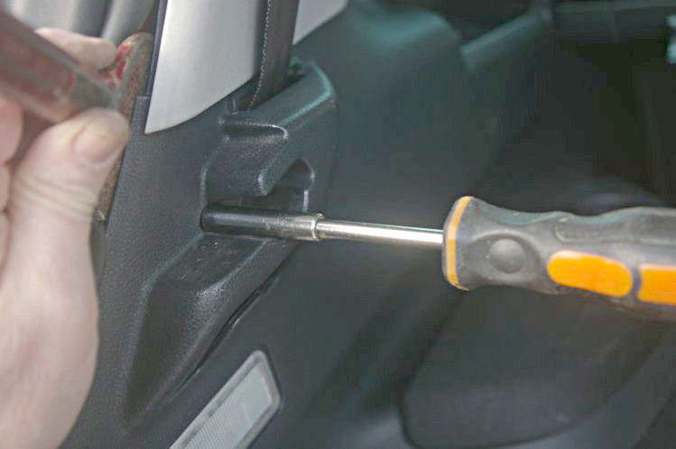
Here is one of those clips mentioned earlier, which you will need to remove from below the main panel.
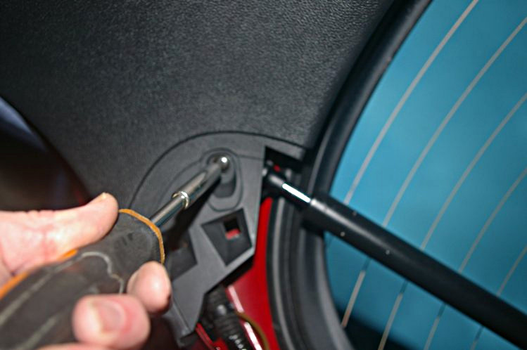
You will also have to undo the bolts in the recesses.
Now you can lever off the panel. An assistant will be a great help here.
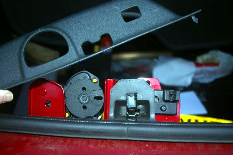
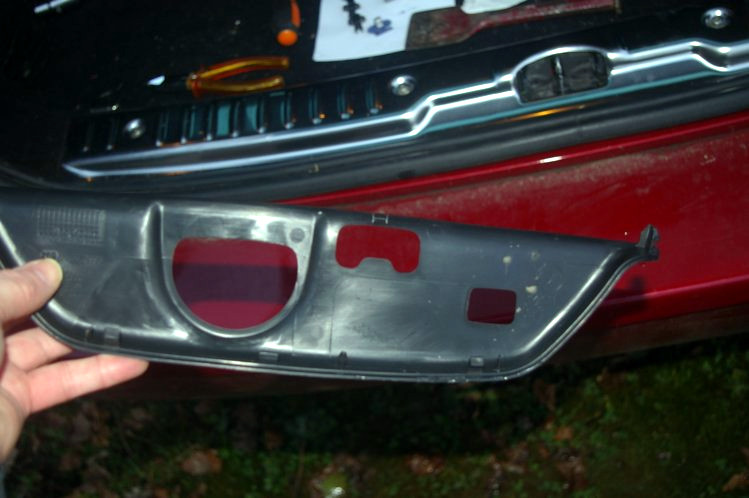
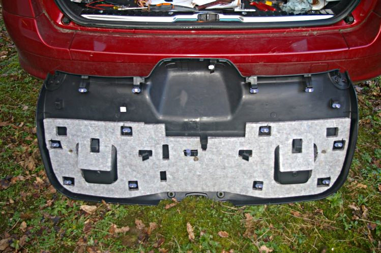
This shows the main panel, removed, with its clips, etc.
Stage D - Attaching the camera.
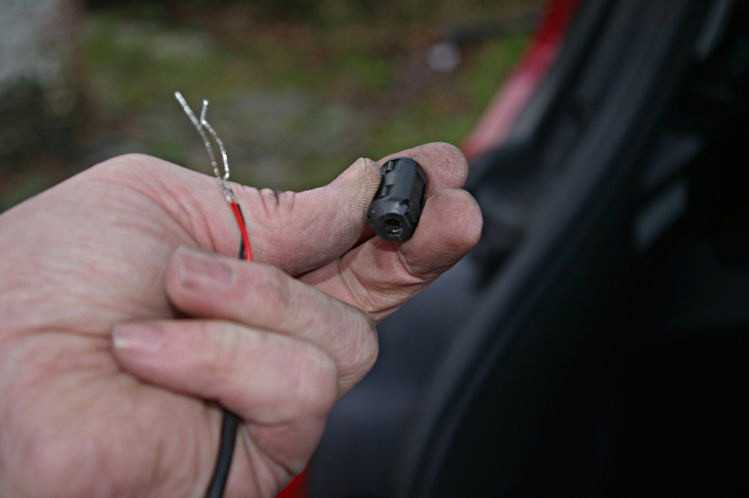
Firstly, if there is one, remove the widget from around the cable and put it aside for refitting later.
Select where you want to mount the camera, considering that you shouldn't (legally) block the view or lighting of your number plate and that you don't want to block the switch for opening the door.
Consider which way up the camera will be fitted - some camera systems allow for converting the image if the camera is upside down but some (eg. my AUTO-VOX) do not. You may need to turn the camera within its mount if that is possible.
If required, drill two holes in the camera backplate large enough to feed you screws (or pop-rivets, etc.) through.
Now position the camera on the back door, over some masking tape, and mark the centre of the holes.
Next, drill holes for the screws, etc. the correct size for them to bite into the metal. Do not slip and make a mess of your door! It's also a good idea to place a cloth inside the panel to catch the swarf.
You will also need to drill another hole for the wire.
This shows the AUTO-VOX camera screwed in place (above the number plate position).
You can see that washers fitted around the screw meant that drilling the backplate was not required.
Make sure it ends up horizontal.
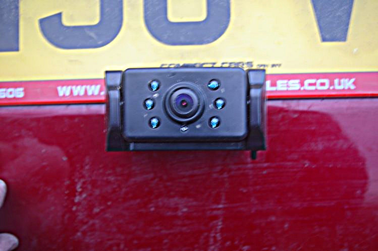
This shows the Ring camera screwed in place (below the number plate position) - with silicone sealant around the various holes, etc.
Make sure it ends up horizontal.
This shows the AUTO-VOX camera in place, tilted down to allow a better view of the distance to another car and to show kerbs, etc.
This shows the Ring camera in place - with a certain jaunty angle showing that I didn't get it quite level.
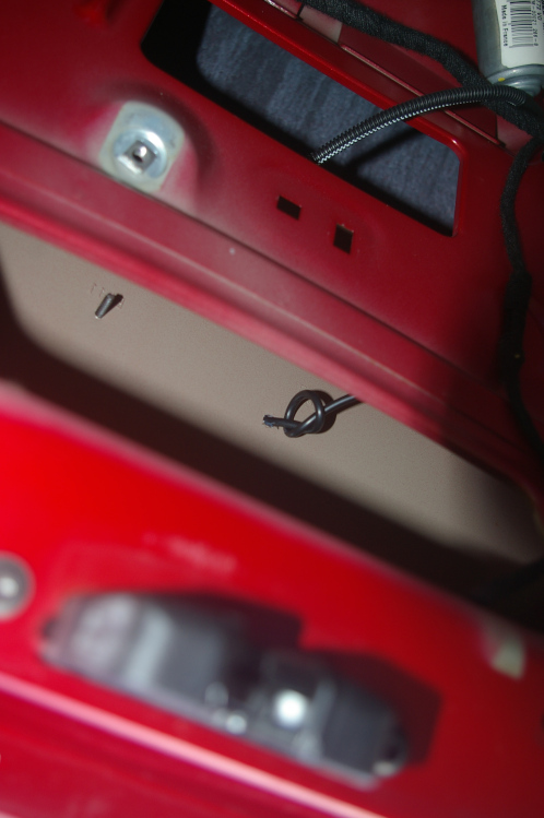
This shows the cable from the camera, inside the door, where I have simply tied a knot to prevent potential thieves pulling the cable through.
Don't forget to refit the cable through the widget before connecting up.
Trim the supplied cable to long enough to reach the wiper. Be very careful doing this since the wires are very thin. Don't forget that you cannot shorten the cable between camera and transmitter (if your system has them seperate).
Now is a good time to solder all the connections - it'll save trouble later on since the wires are usually very thin and give a poor connection.
Connect the camera live wire to the end of wire you installed earlier, using a connecting block.
Stage E - The earth connection.
The wiper mounting bolts are 10mm.
Loosen one bolt and fasten the earth wire under it.
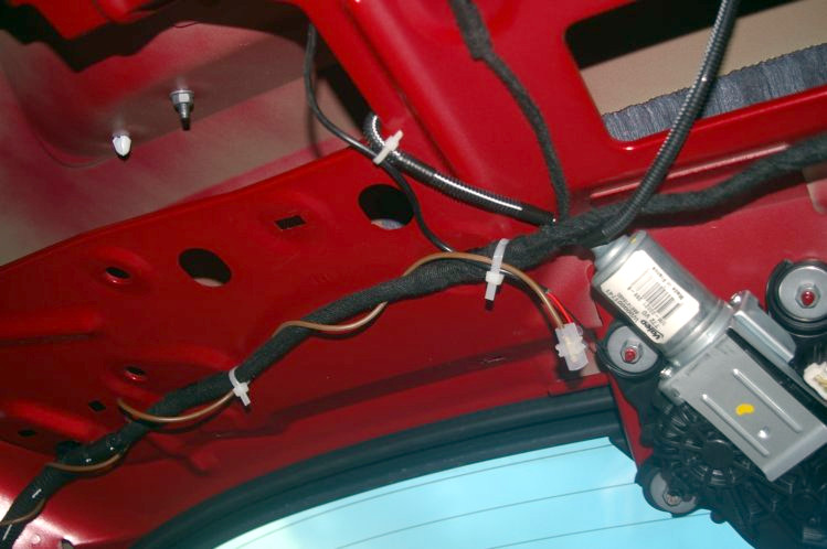
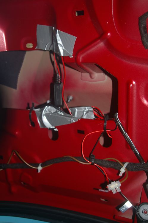
Now use cable ties or gaffer tape to fix the wires in place - thus preventing any rattling.
If your camera system has a separate transmitter then tape / clip it so that it is in a gap in the metal panelling and is vertical (to get the best signal).
Stage F - Running the live cable through the rear door.
Now tuck the power lead into the side of the window, using gaffer tape and / or cable ties as required to keep it out of the way of the fixing clips for the cover panel.
Stage G - Running the live cable into the car body and down.
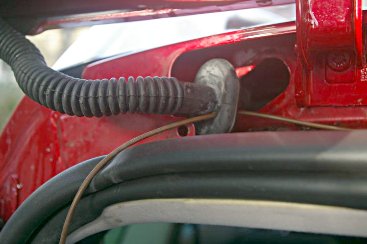
Unless you are very clever you will not be able to run the cable through the concertina tube which connects the door to the car body.
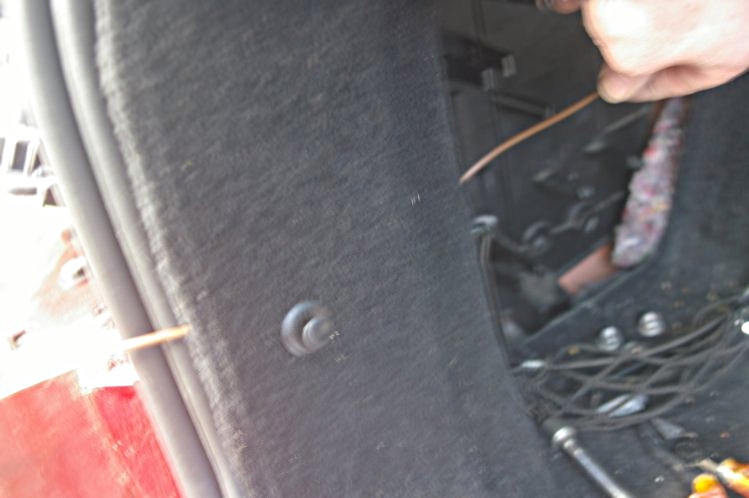
Lever out the large grommet from wher the wires enter the car body.
Drill a small hole towards the bottom of the grommet and feed the wire through it.
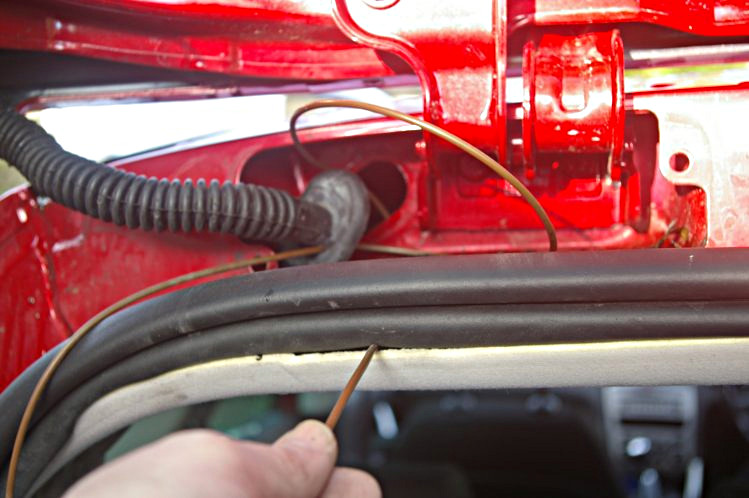
There is now an awkward panel inside the roof which you will need to feed the wire around and then down into the space over the headlining.
The headlining needs to be eased out of the rubber seal at this point.
The wire needs to be bent so as to be reachable with tongs (or very long thin fingers, etc.).
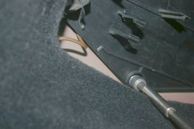
The side panel only needs easing out at the back in order to slide the wire behind it.
However you do need to remove the T20 bolt near the luggage clip, which holds it in place.
Now unclip the toolkit cover.
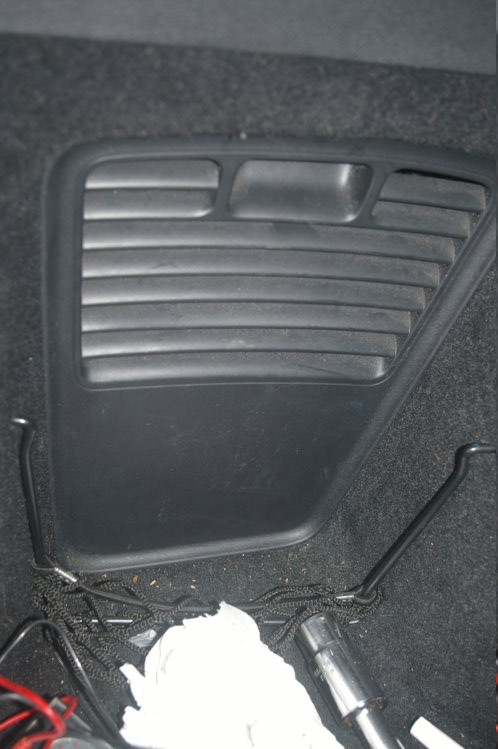
The wire needs to be fed down in the side panels until it goes through into the toolkit area.
The inside mounting panel is attached witha 10mm bolt which needs to be loosened off.
The toolkit frame does not seem to remove, but can be worked around.
Finally, for this stage, refit the large rubber grommet, above the door, and then clip the wire to the concertina tube with cable ties.
Stage H - Removing the light cluster.
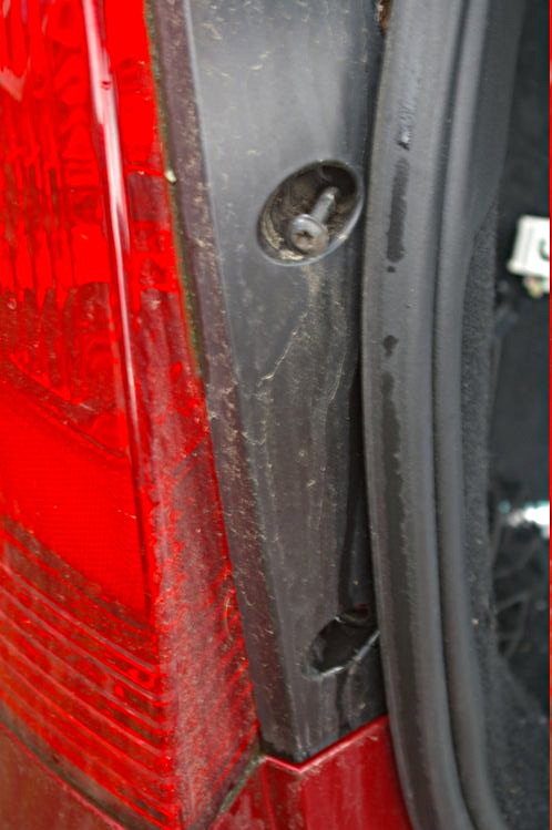
Undo the left hand rear light cluster.
This has two T30 bolts, as shown, which lock it to the car body.
Start as you mean to go on and put them somewhere safe, ideally on a piece of paper with a note where they came from.
Ease the light cluster to the left and up. This will free the push-fit thingummy at the top.
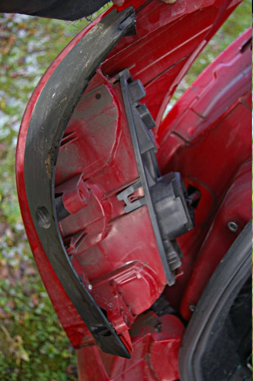
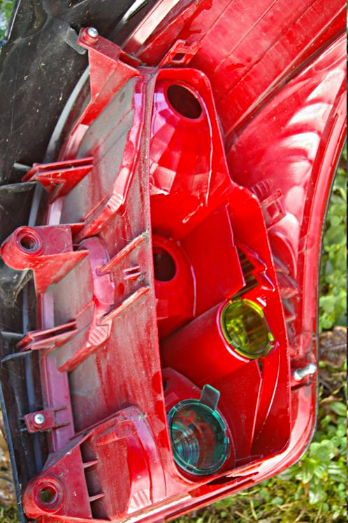
Here's what the inside of the light cluster looks like with the reverse bulb at the bottom.
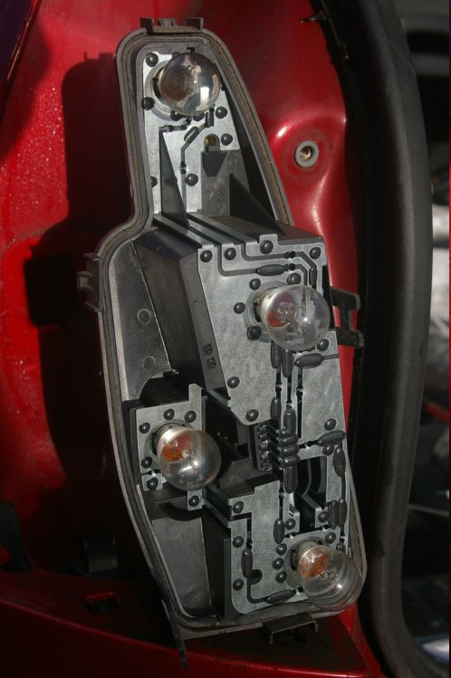
Here is the main body of the light cluster showing the inane blue filter which dims the reverse light.
It's presumably there to stop red light coming from the red coating over part of the lens - a triumph of form over function.
This brings me to mention how to see more when you are reversing, since the reversing light is so feeble. I usually take my foot off the throttle and let the car creep along, but I touch the brake peddle and thus get the brake lights to see by.
You may find this necessary with the reversing camera as well since its built-in lights are quite limited in range.
Stage J - Connecting the live cable.
Locate the wire inside the light-unit feed hole and pull it through using a hook or kitchen tongs.
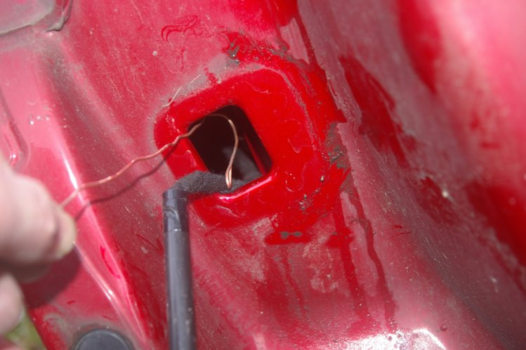
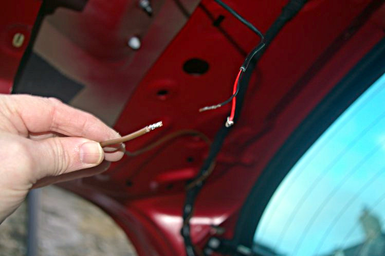
Here is the pulled-through wire.
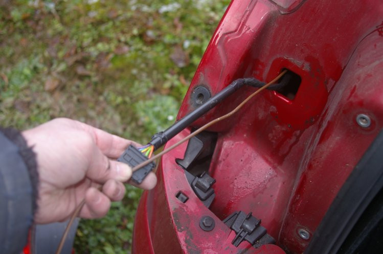
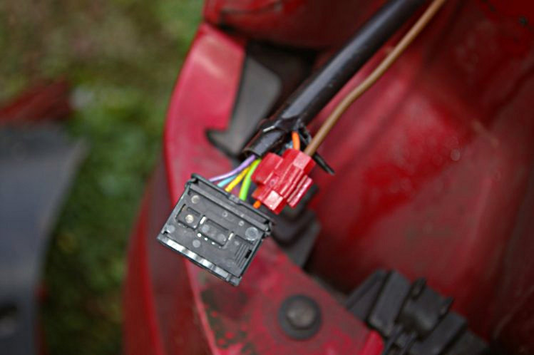
Trim back the sheath around the cable leading to the connector. Do not cut through any of the wires.
On my car the cable for the reverse light is orange.
You will need to make sure of the one which leads to your reverse light by tracing the connection through to the bulb.
Don't think that a Haynes Guide will help here since the wiring diagram in it doesn't even show the reverse light at all.
When you think you have found the correct lead, try seeing if you can test it with a multi-meter or a 12V bulb. You will need to switch the ignition to it's first stop (before starting the engine) and then select reverse gear. Do be careful not to actually start the engine and crash your car!!! However, don't do too much testing this way and end up with a flat battery.
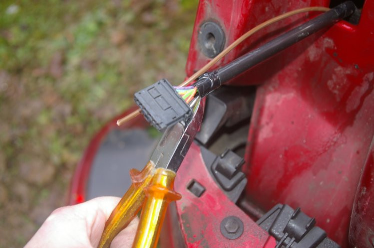
Now for the fiddly connector supplied. It helps if you lever the jaws apart before trying to fit it over the wire.
Stage K - Testing and reassembly.
Before reassembly, check that the camera is working.
It is easiest to plug the monitor into the accessory socket at the rear side of the car.
Now all you need to do is put everything back together again - in the reverse order of taking it apart.
Be especially careful with forcing the panels back in place, to ensure that you haven't got the new wire over where any clip / bolt will go.
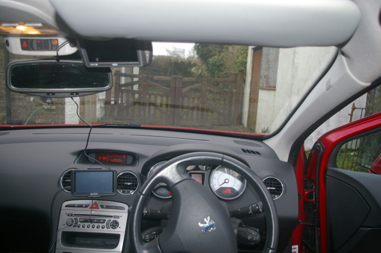
Stage L - Select where to mount the monitor.
I recommend trying various places before settling on one and tidying up the wiring.
The screen position is critical to its use so try it first with loose-laid wires before finalising its position and power source.
Please bear in mind that the right-hand column contains an airbag - so avoid anywhere which could end up with the bag hitting you round the head with the monitor. Also, avoid fiddling around with inserting the wires in the bag's vicinity.
I've ended up fitting the monitor on the triangular window on the door.
If you don't have a SatNav then you could consider using a vent mount over the silly central air vent.
If you have problems with the AUTO-VOX mount's sucker melting, then alcohol is recommended for cleaning it off.